资源简介
详细介绍了锁相环的原理,并给出了一个基于matlab的仿真程序,对理解锁相环的原理非常有用!

代码片段和文件信息
%频偏:-60Hz
%相偏:在0--2*pi内随机分布
%QQ:22069605
%程序及结果如下:
clear all;
close all;
%定义锁相环的工作模式:单载波为“1”、BPSK调制为“2”、QPSK调制为“3”
PLL_Mode = 1;
%仿真数据长度
Simulation_Length=1000;
%基带信号
if PLL_Mode == 1
I_Data=ones(Simulation_Length1);
Q_Data=I_Data;
else if PLL_Mode == 2
I_Data=randint(Simulation_Length1)*2-1;
Q_Data=zeros(Simulation_Length1);
else
I_Data=randint(Simulation_Length1)*2-1;
Q_Data=randint(Simulation_Length1)*2-1;
end
end
Signal_Source=I_Data + j*Q_Data;
%载波信号
Freq_Sample=2400;%采样率,Hz
Delta_Freq=-60; %频偏,Hz
Time_Sample=1/Freq_Sample;
Delta_Phase=rand(1)*2*pi; %随机初相,Rad
Carrier=exp(j*(Delta_Freq/Freq_Sample*(1:Simulation_Length)+Delta_Phase));
%调制处理
Signal_Channel=Signal_Source.*Carrier‘;
snr=20;
Signal_Channel=awgn(Signal_Channelsnr‘measured‘);
%%%%%%%%%%%%%%%%%%%%%%%%%%%%%%%%%%%%%%%%%%%%%%%%%%%%
%以下为锁相环处理过程
%%%%%%%%%%%%%%%%%%%%%%%%%%%%%%%%%%%%%%%%%%%%%%%%%%%%
%参数清零
Signal_PLL=zeros(Simulation_Length1);
NCO_Phase = zeros(Simulation_Length1);
Discriminator_Out=zeros(Simulation_Length1);
Freq_Control=zeros(Simulation_Length1);
PLL_Phase_Part=zeros(Simulation_Length1);
PLL_Freq_Part=zeros(Simulation_Length1);
%环路处理
C1=0.022013;
C2=0.00024722;
for i=2:Simulation_Length
Signal_PLL(i)=Signal_Channel(i)*exp(-j*mod(NCO_Phase(i-1)2*pi));
I_PLL(i)=real(Signal_PLL(i));
Q_PLL(i)=imag(Signal_PLL(i));
if PLL_Mode == 1
Discriminator_Out(i)=atan2(Q_PLL(i)I_PLL(i));
else if PLL_Mode == 2
Discriminator_Out(i)=sign(I_PLL(i))*Q_PLL(i)/abs(Signal_PLL(i));
else
Discriminator_Out(i)=(sign(I_PLL(i))*Q_PLL(i)-sign(Q_PLL(i))*I_PLL(i))...
/(sqrt(2)*abs(Signal_PLL(i)));
end
end
PLL_Phase_Part(i)=Discriminator_Out(i)*C1;
Freq_Control(i)=PLL_Phase_Part(i)+PLL_Freq_Part(i-1);
PLL_Freq_Part(i)=Discriminator_Out(i)*C2+PLL_Freq_Part(i-1);
NCO_Phase(i)=NCO_Phase(i-1)+Freq_Control(i);
end
%画图显示结果
figure
subplot(221)
plot(-PLL_Freq_Part(2:Simulation_Length)*Freq_Sample);
grid on;
title(‘锁相环频率响应曲线‘);
axis([1 Simulation_Length -100 100]);
subplot(222)
plot(PLL_Phase_Part(2:Simulation_Length)*180/pi);
title(‘锁相环相位响应曲线‘);
axis([1 Simulation_Length -2 2]);
grid on;
%设定显示范围
Show_D=300; %起始位置
Show_U=900; %终止位置
Show_Length=Show_U-Show_D;
subplot(223)
plot(Signal_Channel(Show_D:Show_U)‘*‘);
title(‘进入锁相环的数据星座图‘);
axis([-2 2 -2 2]);
grid on;
hold on;
subplot(223)
plot(Signal_PLL(Show_D:Show_U)‘r*‘);
grid on;
subplot(224)
plot(Signal_PLL(Show_D:Show_U)‘r*‘);
title(‘锁相环锁定及稳定后的数据星座图‘);
axis([-2 2 -2 2]);
grid on;

figure
%设定显示范围
Show_D=300; %起始位置
Show_U=350; %终止位置
Show_Length=Show_U-Show_D;
subplot(221)
plot(I_Data(Show_D:Show_U));
grid on;
title(‘I路信息数据‘);
axis([1 Show_Length -2 2]);
subplot(222)
plot(Q_Data(Show_D:Show_U));
grid on;
title(‘Q路信息数据‘);
axis([1 Show_Length -2 2]);
subplot(223)
plot(I_PLL(Show_D:Show_U));
grid on;
title(‘锁相环输出I路信息数据‘);
axis([1 Show_Length -2 2]);
subplot(224)
plot(Q_PLL(Show_D:Show_U));
grid on;
title(‘锁相环输出Q路信息数据‘);
a
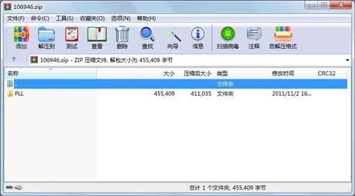
属性 大小 日期 时间 名称
----------- --------- ---------- ----- ----
目录 0 2011-11-02 16:44 PLL\
文件 3237 2011-10-26 11:10 PLL\PLL.m
文件 452172 2011-10-26 14:43 PLL\锁相环原理.pdf
相关资源
- 组合导航matlab程序
- 替代数据法的matlab程序
- 神经网络分类matlab程序
- matlab程序用Hopfield网络解决TSP
- 多用户检测MATLAB程序
- 实现2ask.4ask.2fsk.4fsk.qam16.qam8调制的m
- 曲线旋转得到曲面的MATLAB程序
- 主动轮廓模型算法matlab程序
- Lozi混沌系统相关分析的MATLAB程序
- 用蚁群算法求解TSP问题的matlab程序
- 分数阶chen混沌matlab程序
- 基于粒子群算法的非合作博弈的matl
- KF+EKF matlab程序实现
- 圆拟合matlab程序,以及圆心 半径的确
- stlwritematlab程序
- 层次分析法的matlab程序
- 泊松过程的模拟及检验 matlab程序
- 世上最牛的23个图像跟踪算法MATLAB程序
- 散点拟合平面的MATLAB程序
- 信号检测与估计-理论与应用答案及
- ROC曲线MATLAB程序
- dijkstra算法改进的matlab程序能求出两点
- EEMD的MATLAB程序
- 基于遗传算法的机器人路径规划matl
- 基于自适应压扩法降低OFDM系统的峰均
- 求露点温度matlab程序
- 计算图像Spatial Frequence的Matlab程序SF
- 德州扑克获胜概率计算的MATLAB程序
- 数模美赛常用模型算法matlab程序包+数
- 遗传算法完整MATLAB程序实数法,轮盘
 川公网安备 51152502000135号
评论
共有 条评论