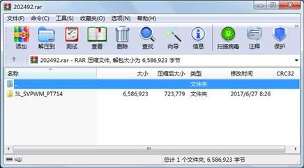
资源简介
本程序为基于dsp28335设计的三电平的svpwm,CCS6及以上都可导入工程直接运行,可以参考

代码片段和文件信息
//###########################################################################
//
// FILE:	DSP2833x_Adc.c
//
// title:	DSP2833x ADC Initialization & Support Functions.
//
//###########################################################################
// $TI Release: 2833x/2823x Header Files and Peripheral Examples V133 $
// $Release Date: June 8 2012 $
//###########################################################################

#include “DSP2833x_Device.h“     // DSP2833x Headerfile Include File
#include “DSP2833x_Examples.h“   // DSP2833x Examples Include File

#define ADC_usDELAY  5000L

//---------------------------------------------------------------------------
// InitAdc:
//---------------------------------------------------------------------------
// This function initializes ADC to a known state.
//
void InitAdc(void)
{
    extern void DSP28x_usDelay(Uint32 Count);
    // *IMPORTANT*
	// The ADC_cal function which  copies the ADC calibration values from TI reserved
	// OTP into the ADCREFSEL and ADCOFFTRIM registers occurs automatically in the
	// Boot ROM. If the boot ROM code is bypassed during the debug process the
	// following function MUST be called for the ADC to function according
	// to specification. The clocks to the ADC MUST be enabled before calling this
	// function.
	// See the device data manual and/or the ADC Reference
	// Manual for more information.
	EALLOW;
	SysCtrlRegs.PCLKCR0.bit.ADCENCLK = 1;
	ADC_cal();
	EDIS;
	// To powerup the ADC the ADCENCLK bit should be set first to enable
    // clocks followed by powering up the bandgap reference circuitry and ADC core.
    // Before the first conversion is performed a 5ms delay must be observed
	// after power up to give all analog circuits time to power up and settle
    // Please note that for the delay function below to operate correctly the
	// CPU_RATE define statement in the DSP2833x_Examples.h file must
	// contain the correct CPU clock period in nanoseconds.
    AdcRegs.ADCTRL3.all = 0x00E0;  // Power up bandgap/reference/ADC circuits
    DELAY_US(ADC_usDELAY);         // Delay before converting ADC channels

    /*自定义配置*/
	AdcRegs.ADCTRL1.bit.ACQ_PS = 0x3;		//采集窗口的大小
	AdcRegs.ADCTRL3.bit.ADCCLKPS = 0x1;		//内核时钟分频器
	AdcRegs.ADCTRL1.bit.SEQ_CASC = 1;		//级联模式,SEQ1和SEQ2作为一个16状态排序器工作
	AdcRegs.ADCTRL3.bit.SMODE_SEL=0; 		//设置顺序采样模式
	AdcRegs.ADCMAXCONV.all		 =15;      	//设置最大通道数(通道数-1)
	AdcRegs.ADCREFSEL.bit.REF_SEL=0;  		//参考基准电压的选择,当前选择外部参考电压基准,为2.048V
	AdcRegs.ADCCHSELSEQ1.all=0x0000;
	AdcRegs.ADCCHSELSEQ2.all=0x0000;
	AdcRegs.ADCCHSELSEQ3.all=0x0000;
	AdcRegs.ADCCHSELSEQ4.all=0x0000;

	AdcRegs.ADCCHSELSEQ1.bit.CONV00=0x0;     //A0U1V1
	AdcRegs.ADCCHSELSEQ1.bit.CONV01=0x1;     //A1U2V2
	AdcRegs.ADCCHSELSEQ1.bit.CONV02=0x2;     //A2U3V3
	AdcRegs.ADCCHSELSEQ1.bit.CONV03=0x3;     //A3U4V4
	AdcRegs.ADCCHSELSEQ2.bit.CONV04=0x4;     //A4U5V5
	AdcRegs.ADCCHSELSEQ2.bit.CONV05=0x5;     //A5U6V6
	AdcReg
属性 大小 日期 时间 名称
----------- --------- ---------- ----- ----
文件 513 2015-05-31 12:04 3L_SVPWM_PT714\V0.0\.ccsproject
文件 23475 2016-07-15 09:39 3L_SVPWM_PT714\V0.0\.cproject
文件 4403 2016-07-14 21:21 3L_SVPWM_PT714\V0.0\.launches\3L_SVPWM_20160324_Ma.launch
文件 4569 2017-06-07 16:22 3L_SVPWM_PT714\V0.0\.launches\3L_VSVPWM_PT714.launch
文件 845 2016-07-15 09:39 3L_SVPWM_PT714\V0.0\.project
文件 62 2016-03-30 11:41 3L_SVPWM_PT714\V0.0\.settings\org.eclipse.cdt.codan.core.prefs
文件 123 2015-05-31 12:04 3L_SVPWM_PT714\V0.0\.settings\org.eclipse.cdt.debug.core.prefs
文件 894 2015-06-01 22:36 3L_SVPWM_PT714\V0.0\.settings\org.eclipse.core.resources.prefs
文件 7270 2015-05-31 12:04 3L_SVPWM_PT714\V0.0\28335_RAM_lnk.cmd
文件 40435 2016-03-22 10:19 3L_SVPWM_PT714\V0.0\Debug\3L_NVSVPWM_UNP_UCMV_20160322_Ma.map
文件 197228 2016-03-22 10:19 3L_SVPWM_PT714\V0.0\Debug\3L_NVSVPWM_UNP_UCMV_20160322_Ma_li
文件 39715 2016-07-14 21:21 3L_SVPWM_PT714\V0.0\Debug\3L_SVPWM_20160324_Ma.map
文件 180430 2016-07-14 21:21 3L_SVPWM_PT714\V0.0\Debug\3L_SVPWM_20160324_Ma.out
文件 193730 2016-07-14 21:21 3L_SVPWM_PT714\V0.0\Debug\3L_SVPWM_20160324_Ma_li
文件 40425 2016-03-24 11:27 3L_SVPWM_PT714\V0.0\Debug\3L_VSVPWM_20160324_Ma.map
文件 197214 2016-03-24 11:27 3L_SVPWM_PT714\V0.0\Debug\3L_VSVPWM_20160324_Ma_li
文件 39710 2017-06-07 15:45 3L_SVPWM_PT714\V0.0\Debug\3L_VSVPWM_PT714.map
文件 180314 2017-06-07 15:45 3L_SVPWM_PT714\V0.0\Debug\3L_VSVPWM_PT714.out
文件 193721 2017-06-07 15:45 3L_SVPWM_PT714\V0.0\Debug\3L_VSVPWM_PT714_li
文件 1770 2017-06-07 16:22 3L_SVPWM_PT714\V0.0\Debug\ccsObjs.opt
文件 289 2017-06-07 15:45 3L_SVPWM_PT714\V0.0\Debug\DSP2833x_common\cmd\subdir_rules.mk
文件 344 2017-06-07 15:45 3L_SVPWM_PT714\V0.0\Debug\DSP2833x_common\cmd\subdir_vars.mk
文件 289 2017-06-07 15:45 3L_SVPWM_PT714\V0.0\Debug\DSP2833x_common\lib\subdir_rules.mk
文件 670 2017-06-07 15:45 3L_SVPWM_PT714\V0.0\Debug\DSP2833x_common\lib\subdir_vars.mk
文件 13570 2017-06-07 15:45 3L_SVPWM_PT714\V0.0\Debug\DSP2833x_common\source\DSP2833x_Adc.obj
文件 5429 2017-06-07 15:45 3L_SVPWM_PT714\V0.0\Debug\DSP2833x_common\source\DSP2833x_Adc.pp
文件 1345 2017-06-07 15:45 3L_SVPWM_PT714\V0.0\Debug\DSP2833x_common\source\DSP2833x_ADC_cal.obj
文件 1648 2017-06-07 15:45 3L_SVPWM_PT714\V0.0\Debug\DSP2833x_common\source\DSP2833x_CodeStartBranch.obj
文件 5898 2017-06-07 15:45 3L_SVPWM_PT714\V0.0\Debug\DSP2833x_common\source\DSP2833x_CpuTimers.obj
文件 5597 2017-06-07 15:45 3L_SVPWM_PT714\V0.0\Debug\DSP2833x_common\source\DSP2833x_CpuTimers.pp
............此处省略184个文件信息
相关资源
- DSP28335程序片内FLASH搬运至RAM运行的
- 基于DSP28335的直流电机闭环调速
- 永磁同步电机无位置传感器DSP28335代码
- TIDSP28335CAN中文使用手册.pdf
- DSP28335的PMSM的SVPWM电机代码
- dsp28335各外设
- DSP28335串口二阶BOOT源码
- DSP28335中文手册
- 用于DSP28335的编程例程 主要是用于有
- DSP28335TI例程
- ucos ii 在DSP28335上的移植
- dsp28335数据手册 中文版
- ucos2.52在DSP28335上的移植程序,RAM版
- 基于DSP28335的SVPWM,CCS6.0
- dsp28335官方例程
- DSP28335 SYS/BIOS
- DSP28335控制单相逆变器双闭环控制程序
- TI dsp28335浮点运算库
- DSP28335+AD7656+CPLD完整PCB图4层板
- DSP28335最小系统原理图以及PCB文件
- DSP28335+AD7606 SVPWM 电路原理和PCB
- DSP28335开发攻略.pdf
- DSP28335-步进电机
- DSP28335例程以及手把手教你学DSP28335
- TMS320F28335DSP原理与开发编程
- 手把手教你学DSP2812书籍 配套资料光盘
- dsp28335最小系统原理图
- DSP28335做简单的频谱分析fft算法
- dsp28335的pwm程序
- AD7606基于DSP28335的SPI方式下的数据采集
 川公网安备 51152502000135号
评论
共有 条评论